IntroductionI’m not a big fan of Web Logs, but several woodworkers have asked me for updates on my ongoing project of an expanding round dining room table, and this is the easiest way to handle updates. More importantly, I needed an avenue of updating my client without overloading his/her email inbox with photographs. I hadn’t planned on creating a weblog when I started this project, so I hadn’t started taking copious photographs until after I completed some of the initial work. The concept of the table is simple, but achieving it is not:
The table must expand from about 6-feet in diameter to almost 8-feet in
diameter,
but remain predominately round. This table concept has been around for
close to two centuries, but there have been very few attempts to design
a better system beyond the Robert Jupe design of 1835. For that reason
alone, this table is commonly known as a Jupe Table even though Robert
Jupe’s patent only covered the mechanical system, which I don’t use. Since I built the first table ten years ago, I get the same questions asked countless times, so let me address these up front: I will entertain serious inquiries, but please don't email me to ask how much this costs. If that is your first concern, then you cannot afford it. And no, the plans are not for sale. Design CriteriaBefore I had even finished building the first expanding table 10 years ago, I had already formulated a series of improvements to the design to solve a few problems that had hindered me getting the components to fit as tight as I wanted. Since that time, I have also moved forward from a 2-dimensional CADD (Computer Aided Design and Drafting) system, to the world-leading SolidWorks solid modeling design system. Ten years ago the mechanical design took weeks of intensive calculations and layout to create a series of flat pieces and right-angle corners. Today, I am able to create a graceful design of CNC-machined and laser-cut components with tight tolerances and high precision. The new design has close to 150 machine components compared to the dozen of so from the original design, yet it took a fraction of the time to develop. Because this version of the table will be shipping across the country, the design must be robust enough to never need adjusting or tweaking. All components are milled from billet aluminum or solid brass, and sheet-steel components are laser cut. Instead of using cabinet-grade slides with moderate lateral deflection, I specified engineering-grade linear rails and pillow blocks. Wood SelectionThe base material is Ribbon-striped, African Mahogany because it has an incredible chatoyance in natural and high-intensity lighting. For all structural components, I chose 1-inch thick high-density maple plywood (aka Appleply) for its rigidity and stability. Where normal plywood has 5 to 7 plies with voids and defects, Appleply has 17-plies and is guaranteed void-free. The 1-inch thick sheet is hard to locate, and at 3-times the normal price from a 3/4-inch sheet, even I was caught off guard by the cost. For the solid lumber components, I went to one of the few wholesale lumber yards that will permit you to hand-pick exotic lumber. Armed with a parts list, tape measure, and a hand plane; I spent the better part of two hours rifling through the stacks looking for the right dimensional pieces, and then scuff-planing the rough-sawn surfaces to inspect the grain. These planks were so massive, that when I left the lumber yard with 7 or 8 pieces of wood, the back end of my F150 was riding rather low. I planned out the materials so that all eight of the fluted columns would be cut from a single 10/4 (2-1/2 inch) plank, all of the feet would come from the same 12/4 (3 inch) plank, the base from a single 10/4 plank, and the center column from its own 10/4 plank, which was wide enough to not require edge-gluing. It took a few extra phone calls, but I was able to get the face veneer grain- and color-matched on a special order from my lumber yard’s own supplier out of state. |
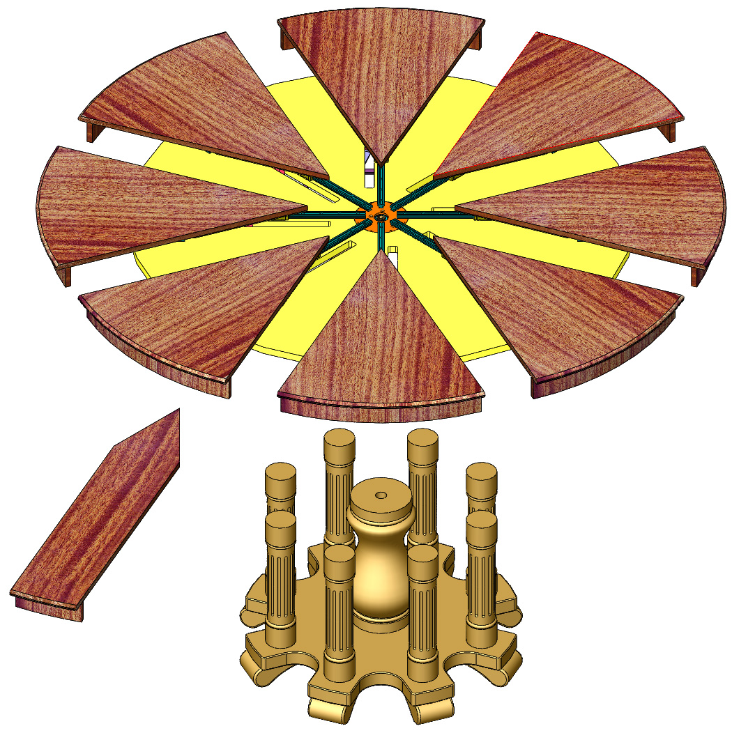 The
Image above shows the primary components of the table. The 8
wedge-shaped pieces splay outward to expand the table, and the
arrow-shaped leaves (only one shown) fit into the gaps.
|
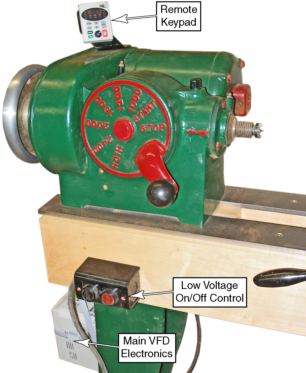
Updating My 60-year-old LatheIt is pretty tough to argue that modern tools can equal the old-iron, and my refurbished Oliver 159 lathe is a turner’s dream to prove it. At nearly 800 pounds, I knew this lathe would handily tackle the massive turnings it was about to encounter, but I wasn’t particularly comfortable with the notion of spinning a 60-pound “tree stump” at the 1200 rpm minimum speed. I spent several nights searching the Internet for a good quality Variable Frequency Drive (VFD) so I could reduce the speed of the motor. I found the Automation
Direct model GS2 VFD to be perfect for
my
needs at a very low cost. It is a fully programmable VFD with a
detachable keypad. So I replaced my bulky 100 pound rotary
phase
converter with this 3 pound electronic controller. I made an angled
bracket from a piece of scrap aluminum and mounted the detachable
keypad
up on the motor housing so I could monitor the motor’s parameters at a
glance. I rewired the original On/Off push button switches from the
lathe to control the VFD, as these are more convenient than pressing
the tiny membrane switches on the keypad. The lathe also had a
stop-switch built into the handle of the reeves drive, but I disabled
this so I could reduce the drive's speed as low as possible without
shutting down the motor. Notice that the reeve drive's speed control is
sitting in the "stop" position in the photograph; this position no
longer stops the motor, but lets me eek out the last little bit of
speed reduction from the drive. To change the frequency (speed) of the VFD, I rotate the tiny
black knob on the keypad. To protect this 60-year old motor, I never
reduce the VFD speed unless the reeves drive is in the Stop (slowest)
position. I use the reeves drive for speeds above 1000 rpm, and the VFD
for speeds below 1000 rpm. |
 |
| NEXT>> |
 |