| I’ve been keeping a bit of a
secret about the table, and I didn’t want to mention it until I knew it
was going to work. Ten years ago when I built the first table, I wanted
it to be motorized, but motor and battery technology just wasn’t
reliable enough. In order to use a motor with enough torque and
reliability, I would have had to have a very large battery. Well today,
motor and battery technology has improved drastically. I’ve been able
to locate a battery operated 3-phase servo motor and compact electronic
controller. OK, here’s the surprise: The table is going to be powered by the internals from a Festool C12 drill motor. This is the only drill in the world that uses a brushless DC, 3-phase, remotely commutated, servo motor. This is an “Intelligent” motor and has all of the electronic features that I need already built in to a compact system. The electronic controller includes thermal overload protection, battery overload protection, battery under-voltage protection, and torque limiting (to protect my mechanics). It would have cost over $2000 to get a motor and controller with all of these features, and I doubt I would have been able to find one that operated on 12 volts, let alone included a pair of batteries and charger. Moreover, this motor comes pre-geared with a 42:1 gear ratio, which coupled with the main gearbox, gives me a 2100:1 overall gear ratio between the motor RPM and the final output shaft. This is very important, because the final output shaft only makes about 1/3 of a revolution, which translates into a motor rotation of only 700 revolutions. The more revolutions, and the higher the motor RPM, the better. Not only does this keep the RPM of the motor at a reasonable level, but it greatly increases the torque output of the motor. A motor torque of just 1 in-oz. translates to 10 ft.-lbs at the output!!!! Two years ago I wrote a technical review of this drill technology, and you can find duplicate copies of my review in vitually every english-speaking country on the planet. The original copy can be downloaded at C12 Review. |
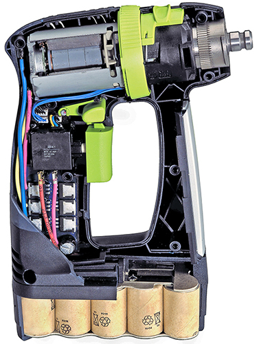 |
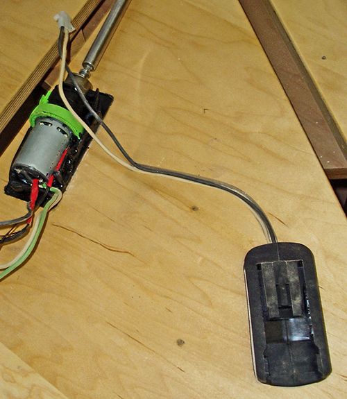
| When the drill chuck is
removed, the exposed drive is a standard
1/4-inch hex drive. So I had the custom input shaft to my gearbox
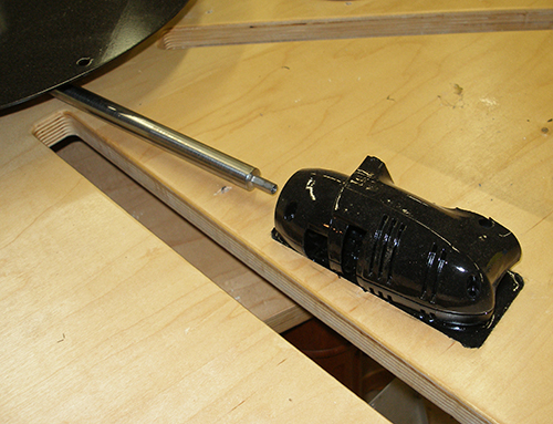
milled with a hex drive for a coupling to the motor. The first hurdle I had to overcome was how to mount the motor and gearbox to the table. Ever since I came up with the idea of using this motor I had envisioned making a 2-piece clamping collar that clamped down on the boss of the gearbox (this is the ribbed cylinder in the picture above). Just as I was getting ready to fabricate a concept prototype, it dawned on me that the existing case of the drill had all of the correct locking and alignment features built-in to lock the gearbox down and prevent it from rotating. It also had a compact and form-fitting enclosure. I milled out a recess in the underside of the table and epoxied one half of the motor housing into the table. I poured the epoxy to be nearly flush with the surface of the table, and used masking tape to prevent making a mess. While the epoxy cured, I wrapped the motor in a thin plastic bag and installed it in the housing, and inserted the main drive shaft into the motor to ensure it was aligned to the primary drive gearbox. This was a pretty risky step, because I still hadn’t worked out the electronic details to make this work yet. Doing this meant I was committing to the concept of a powered drive instead of a manual crank, such as what was used on the original table. |
 |
| Before I could begin prototyping
the wiring for the motor, I realized I needed to finalize the battery
mounting while I still had enough room to get a router in there to mill
out the mortise. I took the same approach as I did with the motor--I
cut the lower battery mount from the drill case and mortised it into
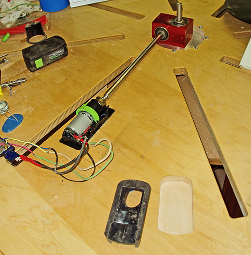
the underside of the table, and then encased it in epoxy. In this picture you can see the exposed motor, the main gearbox (red cube), the battery mount shell (without the battery terminals), and the mortise for the battery mount. The depth of the mortise was set so the battery base would be flush with the underside of the table substrate. This makes it easier for the operator to install the battery into the base by feel, without seeing the mount. Oh, I forgot to mention that I needed to remove the steel sub-frame from the table in order to do this work. The hexagonal support rails pass directly over the top of the motor, so most of this is directly above the main pedestal. |
 |
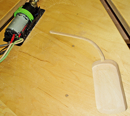
| I didn’t want to have exposed or
lose wires running across the underside of the table, so I created a
smooth-curve-template, and routed a 1/4-inch dado from the battery
compartment to the location of the electronics enclosure. When I poured in epoxy to secure the battery holder, I also filled this dado with epoxy to completely cover the wiring too. The result is a neat and tidy wiring between the battery and the controller. |
 |
| Here is a picture of the battery
wiring before I poured the epoxy. One thing I changed after this
picture was taken is that I also milled out a larger area underneath
the electronics box (discussed below) so the wires could line up with a
hole in the bottom of the electronics box. It also included another set
of wires going to the topside of the table where I will later route
wiring for the control switches. |
 |
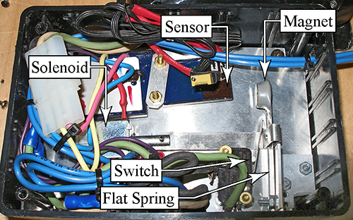
| The biggest hurdle I had to
work out with the electronics was controlling the Forward and Reverse
function. There is no switch to control direction. Embedded inside the
sealed controller (the blue and black square at the top of this
picture) is a sensor that detects the presence of a rare-earth magnet
to determine when the motor should reverse direction. So I needed to
figure out a way to move a magnet into position to reverse the table.
Compounding this, the magnet needs to be in position before the
controller gets power, otherwise it locks out the signal. (This
prevents the motor from being reversed while it is running at-speed.) I have been pondering this problem for months while I built the rest of the table, and I had tossed around a lot of different ideas. The bottom line that dictated the solution was that it had to be completely transparent to the operator and be easy to deal with. This ruled out mechanical levers, which I had considered early on. So I decided to use a solenoid to pull a magnet (gray disk of epoxy in upper right corner) into position. It took a lot of tweaking to determine the sweet-spot in the design where I could be ensured that the magnet (a very powerful one) was far enough away when not engaged, yet close enough to be detected when engaged. About half way through the trial process, I discovered that changing the polarity of the magnet gave me a sharper distinction between Fwd and Rev. The solenoid pulls the magnet in, but I needed a spring to return it to its disengaged position. I needed a really light spring with very little force, yet could easily move 1/2 inch. A flat spring really fits the bill, but I can’t exactly get one at the local hardware store. Feeler gauges are made out of spring steel, and moreover, I have a whole range of thicknesses to choose the right stiffness from. A 0.008” gauge was just perfect for a flat spring. The next problem was to prevent the controller from getting power until the magnet was in position. I accomplished this with a micro-switch to detect when the magnet’s spring-arm was in position. When the operator presses the Reverse button, the solenoid is engaged, but the micro-switch interrupts the signal to the motor until the magnet has moved. The micro switch has a long arm on it so the switch can be kept out of the way, and just the arm is in contact with the spring-arm. |
  |
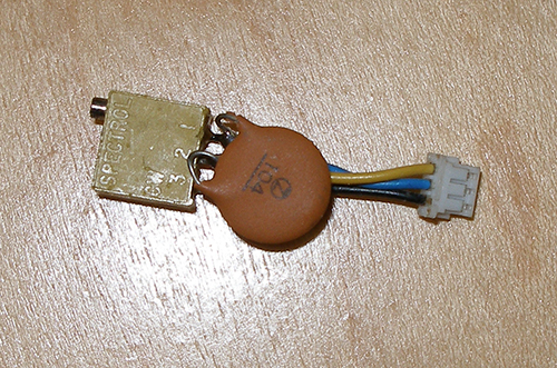
| Most variable speed drills
have all of the motor’s power going through a large variable resistor
in the trigger. However, because the C12 drill is all electronically
controlled, the speed of the motor is controlled by a very small
variable resistor in the trigger, and it is just a tuning circuit for a
pulse generator (also called a clock circuit). I measured the
resistance of the trigger and replaced it with a circuit-board-type
variable resistor that I could use to set the desired motor speed. Once
set, the motor speed will be fixed and not adjustable by the operator. Unfortunately there is also a built-in safety feature of the motor controller that prevents the motor from starting when the speed is much more than zero. In other words, if you are holding the power trigger of the drill in when you replace the battery, the motor will not start until you release the trigger first. This is the opposite of what I need the motor to do. I need the motor to start at the speed I predefine. This new development was such a significant impediment that I really feared it was going to kill the whole concept that I had already fully committed to by this point. In order to get the motor to turn at the speed I needed, I couldn’t get it to start, but a speed that was low enough to get it to start was too low for my needs. Then it hit me that maybe I could fool the controller into thinking the speed was zero for a split-second, but then running at my set-speed from then on. It was a valid concept, but without access to the internal schematic of the controller, it was really just a shot in the dark. I used a spare controller and motor to test out my proof of concept so I didn’t risk damaging the brand new controller installed in the table (Festool sent me a couple warranty/repair controllers and a motor for experimenting with, plus a brand new controller, because I had fried one during my prototyping process). I added a tiny capacitor across two of the terminals of the speed control variable resistor. When the power is first turned on, this capacitor is uncharged and has a zero-voltage. However, once the capacitor has charged, then the resistor takes over and it controls the speed. What was originally a near-killer impediment, had a very simple solution! |
 |
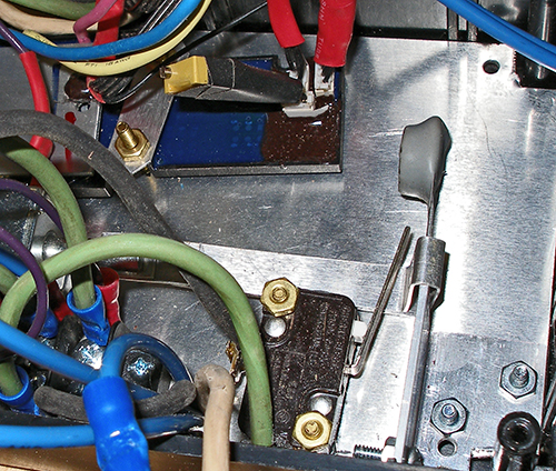
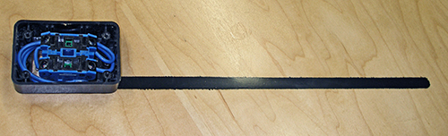
| Here is the final motor
mount and wiring. The loose blue wires are for a limit switch that I
have not yet mounted. This switch will prevent the table from being
opened beyond its maximum size (which would actually start to re-close
the table, but in the wrong direction). One of the concerns I have had for a while is that the 40:1 gear ratio of the red gearbox would magnify the torque of the motor so much (by 40 times) that the torque cutout of the motor would be ineffective, and wouldn’t engage until long after too much torque was applied to the rest of my mechanical system. In other words, I have been very afraid that this motor would be so powerful that it could damage the rest of the system (which it could, if I didn’t have limits in place). I was elated to discover that not only does the torque limiter engage at a low enough level (I can therefore adjust it upward), but I can even run the motor in its low-speed gear configuration, and it still engages. I had previously feared that I needed to keep the motor in its high-speed gearing in order to make this work. I found that I could grab hold of the black disk with my hand and apply enough back-force to engage the torque lockout, which is way below the mechanical danger limit of the mechanics. Therefore, once the rest of the mechanics are installed, I can adjust the torque cutout to be high enough to tightly close the table, but below the threshold of damaging the linkages. This worked out better than I had expected and gives me the control to protect the table from improper use. (The original table from 10 years ago could be damaged if the operator over-cranked the input shaft.) |
 |
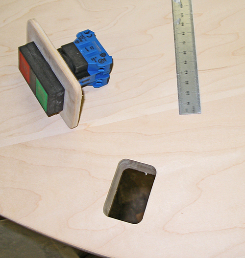
| To control the table, I
wanted a
large enough switch to be easily found by touch, yet small enough to
not protrude below the level of the table skirt. This is an
industrial-grade pushbutton switch-pair with an interlock to prevent
both switches from being pressed simultaneously. As I was developing the circuitry to control the motor, it occurred to me that if someone first pressed the Reverse button, and then pressed both buttons while the table was opening up, this would bypass the limit switch. The table would continue to open beyond the limit switch until it jammed. (The limit switch is mounted on a mechanical limit block, just in case the switch fails.) To start with, I routed a through hole for the switch body. The switch is positioned below the table, but extends up through to the top side of the substrate. The piece of wood is a small riser block for the switch, but I am going to re-cut it to be smaller, closer in size to the face of the switch. |
 |
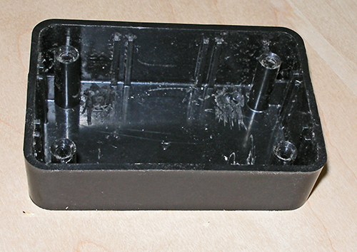
| On the top side of the
substrate
(below the main top) I will use a plastic enclosure to provide access
to the wiring on the switch. This is a two-piece box from Radio Shack.
Originally, the only way I could think of mounting this box was
upside-down without the cover, and screwing it in position from below.
This is why the wooden spacer is so large, but that has since changed. What changed is that I originally didn’t think I could mortise the base of the box into the table tightly enough to look appropriate. When I realized that the fillet radius of the box was a standard 1/2-inch, I figured I could make this fit. I used the Festool MFS guide like I used for milling the pins and sockets, and made a trial mortise in a piece of scrap. The depth of the mortise is necessary so this box remains below the level of the moving tabletop components. |
 |
| Needless to say, I am
thrilled
with the fit! This is a picture of the box-base inside the mortise I
cut. There is no gap, and I can fully press the box to the bottom of
the mortise. The fit is so tight that you can’t even see a shadow line at the corners, or anywhere else. I can press this in with my hand, but I have to wiggle it to remove it!! To finish this up, I used a template router bit to cut the center out of the bottom of the box to match the hole I previously cut in the substrate. This gave me enough flange material for me to screw the bottom of this box down to the table. |
 |
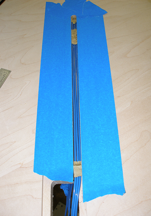
| I next routed a channel for
the
wires to pass between the electronics enclosure to the switch box. At
the top of the picture is where the wire come up through the table from
the electronics enclosure. I dammed up the hole with plumber’s putty to
prevent the epoxy resin from dripping down through the hole, and also
added another glob of putty to keep the wires in the bottom of the
channel after they made the turn from vertical to horizontal. These
globs of putty are below the surface, and will be covered by epoxy. At the bottom of the picture, I built a dam from putty to prevent the epoxy from getting into the mortise for the switch box. Unlike the previous globs of putty that are fully encased inside the epoxy, this dam will be scrapped away when the epoxy dries. I carefully shaped the edge of this dam to align with the edge of the mortise. I poured the epoxy very neatly with no overrun so it actually created a domed meniscus without spilling over into the blue masking tape. Because this wire trough will be visible to the homeowner (but only when changing the table), I poured the epoxy proud of the surface and will sand it flush later. I will reapply the masking tape and paint this black before putting the protective lacquer finish on this side of the table substrate. |
 |
| After the resin dried, I
sanded
the covered wire trough flush with the substrate and then re-masked off
the area with painter’s tape. I painted the wire trough black and then
lacquered the whole top of the substrate. I screwed the switch enclosure box down to the table and routed the wires to the switch contacts. What is not so obvious from these pictures is that the switch push buttons and the switch contacts (the part shown here) are separable, so this lets me position the buttons, and wire the contacts separately. This came in handy because I mistakenly swapped the forward and reverse wires at first. Pressing the button closest to the center of the table closes the table, and vise-versa. This is the most intuitive operation of the switch. With the wiring complete, I screwed the cover down to the switch enclosure. |
  |
Up Next: Things have been so busy lately that I haven't had the time to stop and take pictures for a while, so I am not sure what I can cover next. It all depends on what I have available. |
|
| <<PREVIOUS NEXT>> |
 |