I picked up 3 Oliver industrial lathes last year from a school in
Wisconsin for $150 each. I sold one lathe before I even made the trip
to pick them up, and sold the other a couple of months later. The
third lathe was for myself, which I finally had the free time to
rebuild a couple of weeks ago.
I don't really have any specifications on these lathes, except I suspect they are possibly 1940's vintage, weigh somewhere in the ballpark of 500 pounds, have approximately 1 Hp, 3-phase motors, and use slip pulleys to provide infinite speed adjustment.
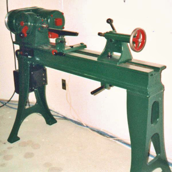
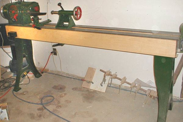
While I should be showing you the "before" picture first, where's
the fun in that? The picture below is of the rebuilt lathe.
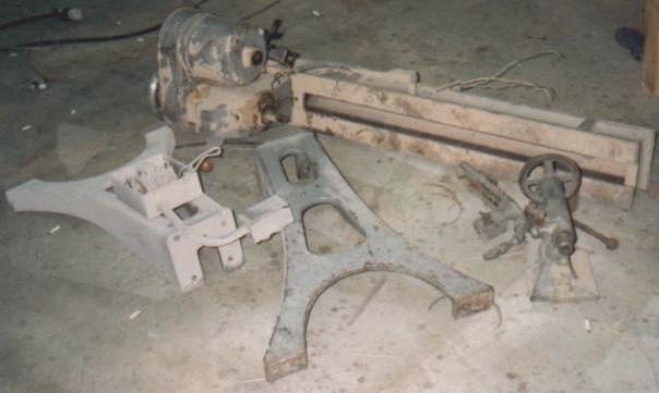
The next picture is what the lathe looked like when I started. (Actually, this picture is of the first lathe which has been sold, but the owner hasn't picked it up yet, since he wanted to wait until I built a phase converter for my lathe. Before he sees my lathe, I am going to try yo buy it back from him. I don't think he is serious about using the lathe, so he probably will sell it back to me if I ask.)
These last two lathes have been sitting under my workbench for the past year in pieces. In order to get them into my truck, I had to take them apart, which is how they have been since. To get them down into my shop, I waited for the first snow, and slid them down the hill like bobsleds. They weigh so much, that the only way to control their speed down the hill was to lay them over on their side as they sped up. One of them almost carried me and my father into the pond behind the shop.
The first thing I needed to do was try to get the legs back on and
stand the lathe up. I knew this wouldn't be easy, but it blew my mind
when I snapped a 2x8 plank like it was a twig while using it as a pry
bar. I ended up putting one leg on under the motor side, and rolling
the lathe upright using a shorter plank. Once it was up on one leg, I
was able to lift the other side up and get it on a sawhorse so I
could bolt the next leg on.
At the time, I hadn't planned on removing the headstock from the bed. If I had, then getting the legs on would have been easy. As I got deeper into the rebuild, I did remove the headstock.
The first thing I did was disassemble the headstock  components. I
removed the bell housing, then the pulleys, the speed control slide,
the spindle, and every thing else which was removable from the
headstock casting. I struggled for a couple of hours trying to remove
the motor from the casting, but I couldn't get the fixed half of the
pulley off the motor's shaft. (Each pulley is comprised of a fixed
disk, and a sliding disk, just like a snowmobile's drive train. Speed
is controlled by sliding the spindle's pulleys together or apart,
while the motor's pulleys are spring loaded to compensate. When the
spindle's pulley plates are close together, the V-belt is forced
outward. The motor's pulleys spread apart to let the belt ride closer
to the shaft. Just like the gears on a ten-speed bike, a small
diameter at the motor and a large diameter at the shaft is low gear.
As the spindle pulleys spread apart, the motor's pulleys tighten up.
This is like high-gear on a bike.)
components. I
removed the bell housing, then the pulleys, the speed control slide,
the spindle, and every thing else which was removable from the
headstock casting. I struggled for a couple of hours trying to remove
the motor from the casting, but I couldn't get the fixed half of the
pulley off the motor's shaft. (Each pulley is comprised of a fixed
disk, and a sliding disk, just like a snowmobile's drive train. Speed
is controlled by sliding the spindle's pulleys together or apart,
while the motor's pulleys are spring loaded to compensate. When the
spindle's pulley plates are close together, the V-belt is forced
outward. The motor's pulleys spread apart to let the belt ride closer
to the shaft. Just like the gears on a ten-speed bike, a small
diameter at the motor and a large diameter at the shaft is low gear.
As the spindle pulleys spread apart, the motor's pulleys tighten up.
This is like high-gear on a bike.)
Even though I couldn't remove the motor completely, I was able to unbolt it and move it around a little to gain access to all sides for sanding and painting. I also removed the bearing housings and inspected the bearings inside the motor.
After all of the parts were removed from the headstock's cast iron housing, I cleaned them up and inspected them. I was amazed at the lack of wear for a tool this old. The machined surfaces were barely even polished from use. It looked like the parts came from the factory.
A good sign was the amount of grease packed into the wear areas of the headstock. These parts had not been run dry. I removed all of the old grease, and re-packed the area with lithium grease, which is a little more fluid and flexible.
I next worked on the tailstock. This also was in very good shape. When I removed the spindle, it was clean, and not pitted. I polished it with a non-metallic scotchpad, and reassembled it after painting. I really take pride in the fact that you can spin the handwheel, and it will continue to rotate for several revolutions before coming to a stop. To achieve the bright, shinny edge of the handwheel (contrasting the Red painted interior), I used the sander to remove the oxidation and tarnishing from the metal. There was very little work done to rebuild the tailstock.
The main chassis (bed and legs) needed little work. I sanded the bed's rail surfaces with my Dynabrade sander until they had a metallic sheen. I also sanded the years of paint from the cast iron in the same manner.
Past History: In the past, the lathe had been repainted by students using Battleship Grey paint, which I fully expect contained high levels of lead. As an Industrial Hygienist, Shame on me, for performing this work without personal protective equipment. I knew full well that there was a very good chance that this paint contained VERY high levels of lead in the paint body, yet I still sanded it off without wearing any type of respiratory equipment. I am registered and fully trained with respect to lead-in-paint contamination, yet I threw this training aside, and did what most woodworkers will do...plodded along as though there was no neurological danger.
With the ugly side, aside, the benefit of this thick-bodied paint was that it filled gouges and grinder marks from the damage caused by the junior high students during previous paintings. As a result, it was like having "bondo" on a car. The small dips and gouges were filled in, and the final surface is moderately smooth. The legs and body of the bed still show that they are sand-cast, yet the headstock and other components are clean and smooth--the way they were when the unit was new.
Painting: I believe that the original lathe was completely grey. I chose to repaint it in green, red, and black, as I have several industrial tools with similar paint schemes and like the appearance. There was little preplanned color scheme to this. I chose each color as I went along. The strong contrast of the red paint looks nice, but too much of it would look poor. On the opposite extreme, I didn't want the entire lathe green either. That's when I started using black for some of the attached parts. Originally, the black was only going to be used for the electrical system, it provided a good look for a few of the smaller pieces. After the painting was completed, the lathe was reassembled.
Phase Converter
It took longer to build the phase converter than it took to
rebuild the lathe itself. I wanted the lathe to be self-contained
including the phase converter. The phase converter is located on the
inside of the left leg. It is the small black box directly below the
on/off switch in the photograph below. On the outside of the left leg
is the magnetic starter, which is also a black painted enclosure. I
don't want to rehash the whole topic of
phase converters. You
can read that in another article on my site. What I do want to cover
is the self-starting nature of this converter. I hadn't fully
completed this part of the converter at the time of the previous
article.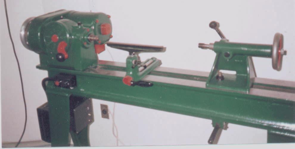
How this works, is when I press the normal start button on the lathe, the starting capacitors are already engaged. As the motor comes up to speed, a relay senses the increase in the third phase voltage. As this relay becomes active, it opens a switch, which disconnects the starting capacitors. As a side effect, if I grab the hand wheel and slow the motor down, the starting circuit re-engages to bring it back up to speed. This is what made me decide to make the unit self-starting. Before I completed the self-starting aspect of the converter, I loaded the motor just to see how much power I was getting. I slowed the motor too much, and it would not come back up to speed. I didn't want this to happen during normal use. The diagram above is the same as the one I used in the Phase Converter article, except I replaced the normal switch with a relay, and added a diode and variable resistor. A very significant benefit to this circuit is that it automatically compensates when the motor is slow to start.
After I managed to build the self-starting converter, I made a
significant observation. When the lathe was set for low speed, the
motor came up to speed quickly, as it's load was low. When the lathe
was set at a higher speed, inertia made the lathe start slower, and
it took longer to come up to full speed. This circuit compensated for
the longer start-time, and remained engaged for a longer period of
time. Had I used the "off-delay timer" as I discussed in the Phase
Converter article, this would not have been the case.
Initial Concept: While I was fine tuning the phase converter's capacitors, I noticed that the voltage from line 2 to the generated line 3 started out at 16 volts before I started the motor. As the motor came up to speed, this voltage gradually increased until it reached its final value of 220 volts. Since the voltage seemed to be related to the speed of the motor, I figured that if I could harness this variation, I could control when the starting capacitors were removed from the circuit. To do this, I needed to come up with a "voltage controlled switch".
Relay: The relay uses the normally closed contacts, which means that when there is no power to its coil, the contacts are touching. The relay's coil is rated for 120 volts at 60 Hz (AC power). Since I am feeding it with 240 volts (actually it is 220 volts in this case), I needed to reduce the voltage. Although I never bothered taking actual measurements, this relay would become active when the coil voltage reached about 70 volts. All I had to do was make sure that the coil's voltage reached 70 volts when the motor was near full speed.
Variable Resistor: The variable resistor acts as a fine tuning control. Some of the circuit's voltage is expended across this resistor. By adjusting the amount of resistance in the dimmer, I control how much voltage the relay gets. I had already burned up a couple of normal variable resistors because they were not rated to handle this kind of current. It suddenly hit me that a dimmer switch for home lighting was cheap, and rated for this kind of power consumption. Since I couldn't find a common variable resistor with large power capabilities, I went to a home center and picked up a common wall dimmer.
As I adjusted the dimmer, the starter control would either turn off too soon, or not at all. By making these adjustments, I controlled how long the starter remained active with respect to the motor's speed.
Diode: I don't know why I needed this, but it was a necessary part nonetheless. My relay was rated to operate on AC voltage. A diode blocks part of the voltage which results in a "sloppy" DC voltage. Without this diode, the system was self-defeating. As soon as the start button was pushed, the starting capacitors resulted in a high enough voltage to activate the relay. The relay would then disengage the capacitors, but they were the cause of the higher voltage. As soon as the capacitors were disengaged, the voltage was too low to activate the relay, and the relay would re-engage the capacitors. The bottom line was that the relay would flicker on and off, but the motor would not start. I fully expected this to happen when I used a DC rated relay, but the AC rated relay shouldn't have done this. I can only surmise that it is because I cut the voltage in half by using the diode.
Explosions: I thought I should mention some of my mistakes as kind of a learning process. At the beginning of experimenting with the relay, I was using a DC rated coil. When it gave the same symptoms that I described above, I placed a small capacitor across the coil's windings in conjunction with a diode. This worked at the time, but something else was giving me problems (which I have forgotten). When the same thing also happened with the AC rated relay, I again placed a capacitor across the windings, only this time, I had a relay which was rated for a much higher voltage. When the voltage was high enough for the relay to engage, the capacitor exploded. This was a small capacitor similar to what you would find in a radio, and was only rated for 35 volts, but when it exploded it sounded like a shotgun blast. Enough current flowed through this tiny capacitor, not much larger than a pencil eraser, to trip the 30 amp breaker back at my load center.
While the main capacitors of the converter are capable of handling this high voltage, the above situation did make me a little jumpy as I was working on different configurations. However, while working with the main capacitors, I was shocked once, but had large sparks. uncountable times. What was happening, I fully anticipated and expected, but I didn't like it nonetheless. When I had a capacitor which was charged up, and connected it to an uncharged capacitor, huge currents would flow for a fraction of a second while the two capacitors equalized. I don't like seeing sparks while I am working on a circuit. As long as the tool is unplugged while making these changes, the chances for harm are actually low, but it is a little disconcerting. To reduce the number of times this happened, I got into the habit of trying to discharge the capacitors before I made changes. I did this by physically lifting the motor's main relay contacts, which discharged the capacitors through the motor.
I admit that there were also a couple of times when I rearranged some of the main capacitors while the lathe was still plugged in. This wasn't by accident; I knew the power was still on. When I did this, there wasn't just a single, short duration spark. The sparks lasted until the connection was completed. I wouldn't recommend doing this. (How is the saying? Do as I say, not as I do?)
 Right now the lathe is complete and running, but I do not have
either a live center, nor a faceplate. The center is a standard
taper, which I can acquire from Delta, but the spindle threads are
not common. I think they are 1-1/8 inch by 9 threads per inch, so I
will have to dig a little to find faceplates for these lathes.
Right now the lathe is complete and running, but I do not have
either a live center, nor a faceplate. The center is a standard
taper, which I can acquire from Delta, but the spindle threads are
not common. I think they are 1-1/8 inch by 9 threads per inch, so I
will have to dig a little to find faceplates for these lathes.
Some New Updates: Since the time this article was originally
written, the lathe has gone through some changes. The first bit of news
is that a woodworker that read this story sent me a couple of
faceplates. Shortly after this, the lathe went through a major
modification. I realized that as a cabinetmaker, 29 inches between
centers was not going to work well for me, so I replaced the cast iron
bed with a massive solid maple and cold-rolled steel twin I-beam. Even
though the wood is less dense than the cast iron, the length of the bed
increased the mass of the lathe significantly.
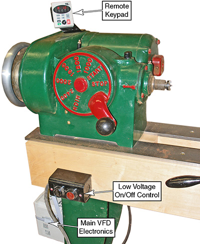 The
next change was to replace the static converter with a Variable
Frequency Drive (VFD). This was the best addition to the lathe I could
make. It gives me electronic speed control, which I use only when I
need to slow the lathe down below the minimum level of the reeves
drive. The model I got is a GS2, and it is capable of separating the
display from the main VFD enclosure. I mounted the display up on the
top of the reeves drive so it was easily visible while I worked.
The
next change was to replace the static converter with a Variable
Frequency Drive (VFD). This was the best addition to the lathe I could
make. It gives me electronic speed control, which I use only when I
need to slow the lathe down below the minimum level of the reeves
drive. The model I got is a GS2, and it is capable of separating the
display from the main VFD enclosure. I mounted the display up on the
top of the reeves drive so it was easily visible while I worked.
