Layout LinesThe base of the pedestal is 2 inches thick and is made from a composite of laminated Appleply and solid mahogany extensions. This will later be laminated with a radial pattern of ribbon striped veneer. I started out by gluing two piece of 1-inch Appleply together to make the 2 inch thick core. Because I needed to cut this square into a perfect octagon, I used drafting-techniques to lay out precise 22.5 degree angles across the square. I first drew diagonal lines across the corners of the square, and lines perpendicular to the sides of the square. Then I used a drafting compass to swing a circle from the center of the square (where all of the previous lines intersected). Where this circle intersected each of the other lines, I swung a series of identical arcs. The intersection of these arc created precise 22.5 degree lines through the center of the square.
|
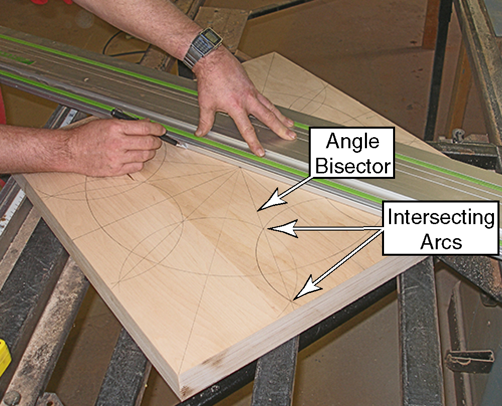 |
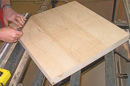
| Where each of these lines
intersected the edge of the square, I drew diagonal lines. These lines
are where the square needs to be cut to create a perfect octagon. . |
 |
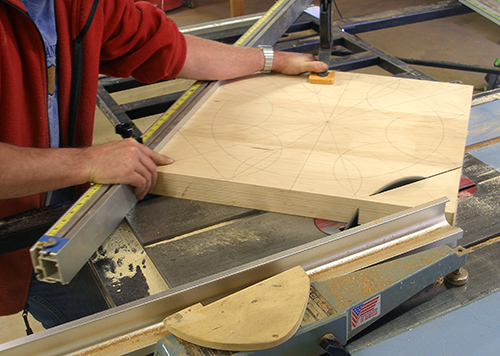
Cutting the Corners
To cut the octagon, I set the tablesaw's sliding table for 45 degrees,
and set the rip fence to the exact position to split the pencil lines
in half with the sawblade. Yes, I broke a cardinal rule for the
tablesaw by using the rip fence with the sliding table, but you will
notice that the corner of the off-cut clears the end of the fence
before the off-cut is fully cut. This is still a fairly dangerous cut,
but I kept a close eye on the triangular off-cut to make sure it won't
get bound up as the cut nears completion. |
 |
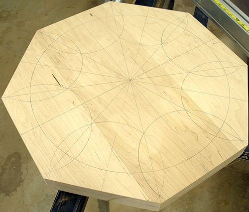
| To confirm the accuracy of the
cuts, I verified that each cut intersected the 22.5 degree lines that I
drew previously. Even though the precision of these cuts is not
critical to the final output of the base, it is helpful when it comes
time to miter the mahogany extension pieces. |
 |
Machining the Extension PiecesI cut the extension pieces from a single plank of mahogany I planed down to 2 inches thick. Using the sliding table and a stop gauge, I cut all 8 extensions identical. Then as necessary, I shaved each block by about 0.001-0.003 inch to fit perfectly onto the core octagon with no visible gaps.Because these extensions will be carrying the full weight of the table, the joints had to be bullet-proof. I used six, 10mm x 50mm Domino tenons per piece; that adds up to 48 tenons and 96 mortises. This would have been impossibly difficult without the Domino joiner. The Domino joiner is so precise in its placement of mortise slots that all 48 tenons fit perfectly without any tweaking or modification, yet they were so tight fitting that I had to use a mallet to drive the tenons into the mortises. This is very impressive! |
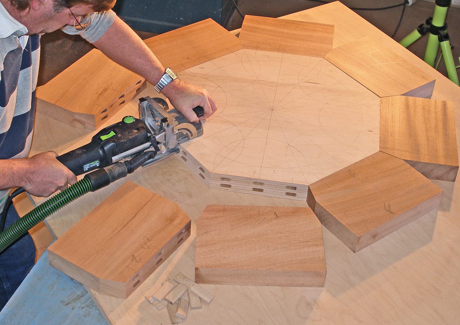 |
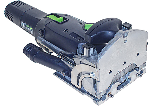
Quick Sidebar on the Domino Tenon JoinerMost woodworkers have never heard of the Domino Tenon Joiner. That's because it will not be released to the U.S. market until April 1, 2007. Festool asked me to write the North American Owner's Manual for the joiner, so I have had an opportunity to use one for a while.Even though the Domino looks like a biscuit joiner, it cuts mortise slots for floating mortise and tenon joinery. In this regard, it has the simplicity of a biscuit joiner with the strength of a floating tenon. A biscuit is a floating spline, but a Domino is a floating tenon. The significance is the strength due to the grain orientation, thickness, and depth of penetration into the wood. This is an expensive tool, about 3-times the cost of a biscuit joiner, but it is well worth it for the work that it can do. I hadn't planned on using the Domino when I first designed this table, but in hindsight, there are many tasks that I could not reasonably complete without it. You'll see more uses of Domino as this project continues. |
 |
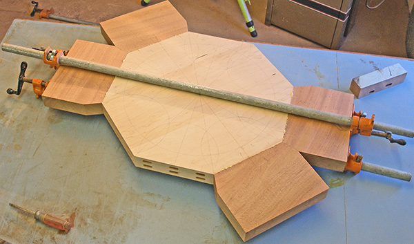
Gluing up the Extensions
Normally when I glue up a mutli-sided miter, I would never consider
doing one piece (or pair) at a time because if a placement error
occurred with one piece, it would cascade through all the remaining
pieces. Because the tenon slots are so precisely placed, I was
successfully able to glue up each segment separately with needing only
a 0.003-inch adjustment to the last piece. |
 |
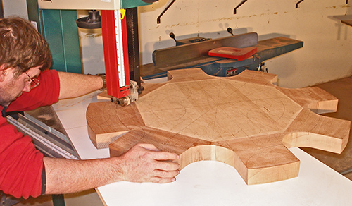
Cutting the ScallopsThe finished base weighs between 30 and 50 pounds, and with its 36-inch diameter, the idea of controlling the piece to cut the curves of the extensions was a little daunting. I added a sheet of melamine plywood to the bandsaw to support the piece while I cut the curves. |
 |
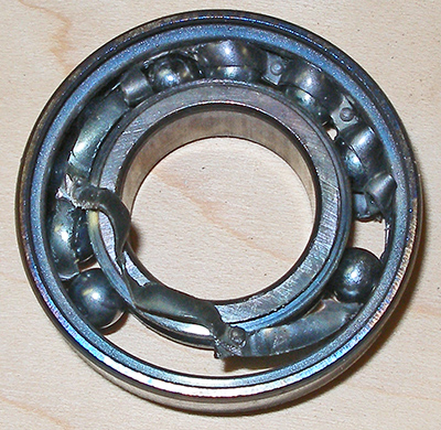
A Sanding SetbackAfter bandsawing the base, I set up a similar melamine extension table for using my horizontal edge sander. About 30-seconds into the first scallop, my sander started to squeal, but I couldn't afford the time to worry about it. By the time I got to the third scallop, the sander was howling like a banshee, and I prayed for just 10 more minutes of work. A few seconds later the bearings completely seized and instantly stopped the belt and motor. I couldn't get to the power switch fast enough, so I yanked the cord out of the wall outlet before the motor was damaged.I took the idler drum off the sander and tried to remove the bearings, but they were so severely seized up that they fused to the axle shaft. A friend brought over his portable hydraulic press and we tried to press the shaft out of the drum. With the idler drum on the bed of the lathe and the hydraulic press pushing up against a steel I-beam supporting my spancrete garage floor, we maxed out the capacity of the press and the bearing still didn't budge. We pushed so hard on the press that I could hear the concrete floor above us moving. Naaaah, I wasn't scared! I was going to throw that pair of underwear away anyway. Well, after a lot of heat from a MAPP torch, and a lot more "persuasion", the shaft finally popped loose and I was able to get the bearings out. I don't think I have ever seen a bearing that was this messed up before! The balls had even fused to the races. These were non-standard bearings, so I had to get replacements from my wholesaler, but of course they were not open on the weekend when I needed them. |
 |
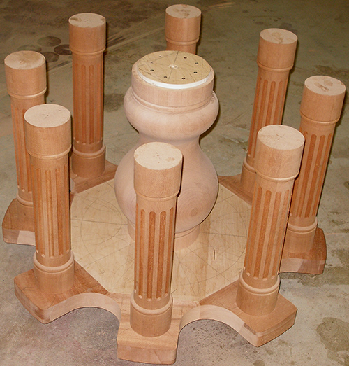
| I used a template guide and a
router to shape the rounded corners of the extensions. This was the
only way I could think of for getting perfectly symmetrical 1/2-inch
radius corners on each extension. It came out even better than I had
though it would. The contrast in the parts in this picture is because some of them have been sanded (the lighter areas) and some are just machined from the router before sanding. (The picture was also over exposed, so I had to do some photoshop manipulating to get the details to show up.) I won't lay down the radial veneer until later. These small triangle-shaped pieces will come out of the same sheet veneer as the table top. Up next is the feet for the pedestal. |
 |
| <<PREVIOUS NEXT>> |
 |