When most woodworkers, professional or amateur, need to square up a tool, they grab their trusty steel square, slap it up to the tool, and poof, the tool must be square, Right? Wrong! Not only is that square probably not square itself, but you are relying on your eye to see a minor squaring error over a rather short length.
When I square any machine, whether it is the Jointer's Fence, Table Saw's Sliding Table, the RAS, or an SCMS, I use mathematics to achieve an even greater level of accuracy than what can be achieved from a standard square. This method is what I call the Double-Error Method. The Double-Error Method (DEM for short) doesn't actually square the tool, but it is a check to make sure the setup was done accurately. This method is more accurate than the best steel square because you are not relying on eyeballing several teeth on the blade to a square's steel edge, but are comparing a saw-cut edge with itself. (This method does not work for adjusting blade run-out however.)
If you were building a house, one degree of error wouldn't be noticeable, but if you were building a chess board, then even 1/100 of a degree is going to show. This is why I developed this method. In the project discussion of the large dining room table, I told you that I needed a miter accuracy on the order of 1/1000 of a degree. This method can achieve accuracies on that order.
Basic Concept
Let's start with the idea of placing a construction square across a
saw's blade. The total length in which the blade touches the square
is less than 3 inches. Furthermore, the camber of the teeth mean that
there is very little flat surface to examine. With this method, you
would be lucky to distinguish an error as large a one full degree.
However, if you had two sharp edges to compare, the human eye could
probably distinguish an error on the order of 1/10 of a degree (this
also depends on the length of the lines). So if we can't distinguish
an error greater than about 1/10 of a degree, then how could I
possibly achieve accuracies of 1/100 or 1/1000 of a degree? This is
where the mathematics come in.
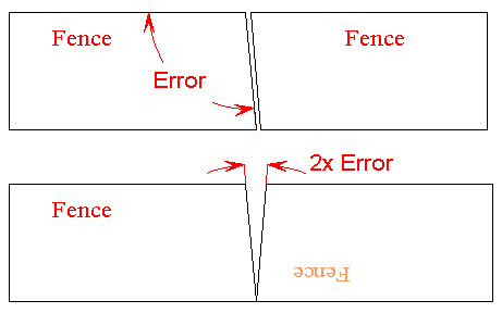
By multiplying the visible error, it will become more noticeable to the human eye. There are two ways to multiply the error. The first is to increase the length of the lines. That is, if you had a framing square which was 8 feet long, your eye could distinguish an error on the order of 50/1000 of a degree. The second method is to make multiple cuts, where each new cut compounds the error further.
Starting Out (Getting Ballpark Settings)
Because getting extremely accurate settings may take several
attempts, I typically use lower quality scrap lumber to start out
with, and use the best available scrap for a final check. Any old
scrap will work to start with to get ballpark settings. For final
checking, I prefer to use white melamine, as the edges are sharp, and
any gap becomes quite noticeable. You could also use Formica, maple,
or any other relatively hard, light colored wood which will
have a sharp edge when cut. A light colored wood accentuates the
darker shadow from a small gap. Melamine particle board is OK for a
saw, but to square a jointer's fence, it needs to be either MDF or
solid lumber. This will be covered below. Also, melamine may not work
for you if your blade chips the edges a lot.
Cross-Cut Saws: For the initial ball-park settings, take a piece of scrap wood which is about 3 inches by 10 inches (the poorest of wood is OK for ball-parking).
SCMS, RAS, and Table Saw Bevel Settings:
To check the bevel setting, or pitch, of a saw, the only thing that
changes from the above procedure is how you cut the wood. Everything
else is the same. When you cross-cut the wood, stand it up against
the fence. When you do your checking on the cast iron table, you
still stand the board up the same as before. This time instead
of marking which side was against the fence, you mark which side was
against the table.
Jointer Fence Setting:
To set the fence on a jointer, the principle is the same, but the
size of the wood is different.
Checking Other Angles Besides 90°
To set up a tool to cut other angles, every thing remains the same,
except you will compare more than just two boards. The level of
accuracy for this setup increases for smaller angles.
I will use a 45° setting to explain this further. Take
a board which has parallel sides, as before. Cut one end of the board
with a 45° miter. 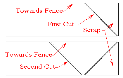
The end of the board is scrap, so you can through it away so it
doesn't get confused with the pieces you want. Now, flip the board
over so that the other edge is against the saw's fence. Do not
change the miter settings of the saw. It must remain exactly where it
is. Make the second cut as shown in the drawing. Even though your
saw was set to cut at 45°, the angle between your two
cuts is 90°. Continue flipping the board and cutting
until you have four triangular pieces.
Once you have four triangles cut, place them together flat on a table with the cut edges touching, and forming a square. If your saw is cutting greater than 45°, you will have a gap in the center of these four pieces. If your saw is cutting less than 45°, you will have a gap at the outside corners. Because it took 2 cuts to make each triangle, and you have 4 triangles, your error will be magnified 8 times. (If you see a 1° error between these boards, this translates to an error at the sawblade of 1/8°.)
To apply this method to other angles, you just need to cut more triangles. For example, to check a 22 1/2° degree miter, you will need to make 8 triangles, and your error will be magnified by 16 times.
