Compound Angles
By Rick Christopherson
Update:
This article was originally written in 1998. I have wanted to
rewrite this article for many years with better graphics and an
online calculator. When Festool-USA asked me to write the owner's
manual for their (then) new Kapex mitersaw in 2009, I finally had
the opportunity to rework this information. However, it was
formatted for PDF output, not HTML. So I did not want to completely
replace this HTML version with a straight link to the PDF. The
information between the two is the same, but the PDF version may use
different variable names, and includes more information than this
HTML version. It also includes additional information regarding
cutting crown moulding using standard miter techniques as well as
compound miter techniques. It also explains how to apply this
information to other applications beyond simple crown moulding.
I recommend reading the PDF instead of this HTML version. If your
internet browser is setup to view PDFs directly in the browser and
the calculator doesn't work for you, then right-click on the link
below and save the file on your computer. Some people have reported
that the calculator does not work on their computer, but I have not
had enough comments to determine under what conditions this may be
happening.
This Compound
Miter (PDF) document is the 3 pages extracted directly from
the Festool Kapex manual. Even if you don't own a Festool Kapex
mitersaw, you may still want to read the entire Kapex
Supplemental Owner's Manual because it contains additional
information that can be applied to your brand of miter saw, such as
calibrating the miter settings using the 4-cut calibration method,
and includes a built-in calculator for that as well.
While there are several different methods for cutting mouldings,
sometimes the best method is to use compound angle settings on a
miter saw, radial arm saw, or a table saw. This isn't necessarily
limited to cutting mouldings though. There are many other
applications where compound miter settings are needed, like the roof
of a doll house for example. Below is a set of equations for
determining the compound angle settings for your miter saw. These
equations will work for any compound angle, but I use crown moulding
around a ceiling as my example, since this is easy to visualize.
In their original form, the equations are very simple and only
use
two variables. To make the equations easier to use in the shop, I
have rearranged the equations in two different forms. These are
all
the same equations, but they are just mathematically
manipulated to help you out. Which equation best suits your needs
will depend on how fluent you are in mathematics, and what
variables
are known when you start. (I have also compiled a
quick reference page to
keep
in your shop. This is just a duplication of the graphic images
shown
below.)
Getting Started
As I stated, there are only two variables needed to use these
equations. The first variable deals with the angle of the room,
picture frame, roof, or how many sides a box has. I have setup my
equations in such a way that it doesn't matter whether you are
making
an inside corner or an outside corner. This is where many
woodworkers
make mistakes because we are not accustomed to working with
numbers
greater than 90°. For example, if you were placing crown
moulding around the top of a square column, other equations would
require you to use the "true" angle of 270°, and if you
didn't,
the results would be abnormal miter settings. The equations I
derived
use the angles the way a woodworker sees them, not a
mathematician.
 FlatMiter
I will call this first variable the FlatMiter (1/2 the
"Corner Angle" used in the PDF version). This variable
is the angle which you would normally set your saw to, in order to
miter a piece of flat moulding. In other words, if you were
putting
crown moulding up around a square room, the FlatMiter would be
45°. The table to the right shows the FlatMiter values
based on how many sides a room or box has.
If your application doesn't fit into the category of being able
to
count the number of sides a box has, you can simply calculate the
FlatMiter variable. Let's say you measured the corner of a box and
found it to be 94° instead of the normal 90°. Then your
FlatMiter variable would be 47°, which is ½ of 94
°.
Remember, with the exception of a triangular frame or the example
above, your FlatMiter variable should always be less than 45°.
Slope
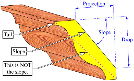 (new graphic added from
PDF) The second variable deals with the slope of the moulding
or the pitch of a roof. Most crown mouldings do not rest against
the
wall at 45°. As a matter of fact, there is no set slope for
crown mouldings. While a 38/52 moulding may be common, it is not
exclusive. The slope of the moulding is dependent on the
manufacturer
and their machine settings.
(new graphic added from
PDF) The second variable deals with the slope of the moulding
or the pitch of a roof. Most crown mouldings do not rest against
the
wall at 45°. As a matter of fact, there is no set slope for
crown mouldings. While a 38/52 moulding may be common, it is not
exclusive. The slope of the moulding is dependent on the
manufacturer
and their machine settings.
While you may know the slope when dealing with a doll house roof,
chances are, you won't know the slope of a specific crown
moulding.
Because of this I have rearranged the equations so that you can
use
Drop-Projection-Width, or just the slope. (Important Note:
Notice that when measuring these variables, they are measured with
respect to the flat side on the back of the moulding. This is
because
the flat side is the surface you place against the saw's table
when
you cut it. If you measure from the face of the moulding, the
slope
of the moulding will be wrong.) Since the Drop-Projection-Width
equation is probably the most useful, I will start with that one.
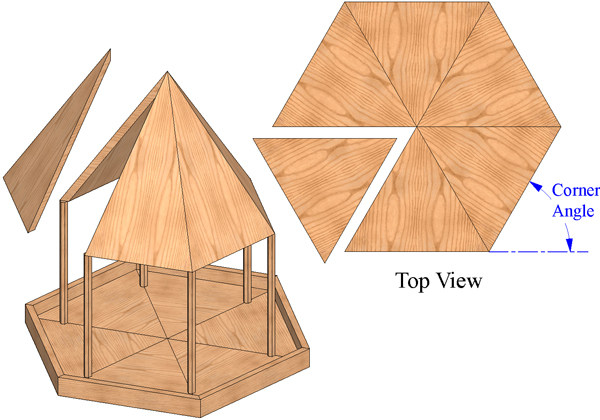
A couple new graphics from the PDF version:
The "Corner Angle" in the
second graphic is a better way of describing the method for
finding the "Flat Miter"
in this original HTML article. The FlatMiter is 1/2 of the Corner
Angle. The Corner Angle is 360 divided by the number sides, and
the Flat Miter is 1/2 of that.
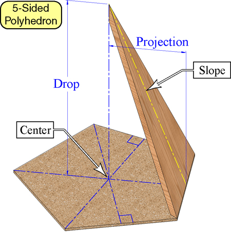
Drop-Projection-Width
If you feel more comfortable holding a tape measure than you
do
with a calculator, then this method is the best. Using a framing
square, measure the Drop, Projection and Width as shown in the
above
drawing. Then apply this into the following Equations:
Slope
If you are familiar with geometry, you may recognize the
"Drop/Width" as the Sine of an angle, and the "Projection/Width"
as
the Cosine of an angle. Just by replacing this information into
the
above equations, we end up with the following:
Unless you are building a three sided box, your miter and bevel
settings should never be greater than 45°. Furthermore,
the calculated compound miter angle should never be equal to or
larger than a flat miter setting.
As I said earlier, these equations can be used for more than just
mouldings. I have used them for many different applications when I
needed a compound angle. The key to this is to visuallize what
your
setup would be like if it was a simple moulding. In otherwords,
picture your application as though it was a moulding placed in the
corner of a room up at the ceiling.
If you found this article from a search engine, and would like to
jump to the Waterfront Woods Home page, click on the image below.

 Email
Rick Christopherson
Copyright 1998, Rick
Christopherson
Email
Rick Christopherson
Copyright 1998, Rick
Christopherson
